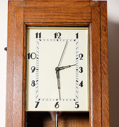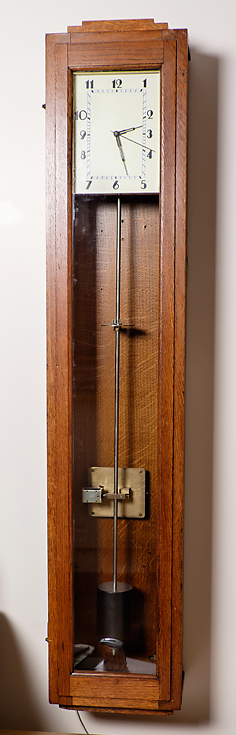
The completed clock.
Full details below
An Electronic Clock Experiment
Electronic Hipp Toggle.
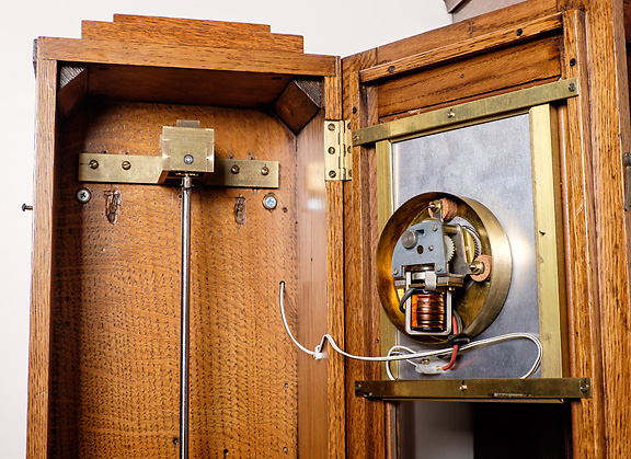
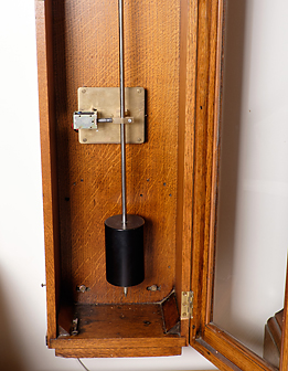
Concept:This Clock started an experiment to replace the mechanical Hipp Toggle arrangement of sensing when a pendulum needs impulsing by an electronic version using a light beam doing the same job. This removes the mechanical interference of the toggle on the pendulum. Originally, it was only in an experimental state, with electronics on a bread-board for easy development (different slave types or sensor arrangements, for example). A Gent's Pulsynetic master clock has provided the case and pendulum. Although similar experiments have been done in the past, I had not heard nor read of any of them when I designed this clock.
Original Design (Version 1):
An opto sensor (IR LED and Photo transistor) is placed to the right
hand side of the pendulum, and the light path is interrupted by a flag
attached to the pendulum rod. The duration of the interruption is used
to detect when the arc of swing of the pendulum reduces below a defined
amount. When this happens, an impulse is given to the pendulum by an electromagnet
on the left side of the pendulum. A second opto sensor placed on the centre
line of the pendulum is interrupted by another part of the same flag to
give 1-second pulses to drive the slave dial. The minimum arc of swing
of the pendulum and the point at which the impulse starts is determined
by the position of the right hand opto sensor with respect to the centre
line of the pendulum. Impulsing occurs on the right-to-left swing of the
pendulum. A separate timer circuit controls the duration of the impulse.
Developed Design:
The functions of the two opto sensors can be combined into one sensor
on the centre line of the pendulum, but this means that the pendulum impulse
could occur in either direction of the pendulum's swing, although in practice
impulse settles to one side or the other. The impulse coils were moved
to below the pendulum bob to give satisfactory impulse in both directions.
The light sensor and the interrupting flag were also moved to the bottom
of the pendulum to give more accuracy. The flag now interrupts the light
beam for most of the time, only exposing it at the extreme of its swing
in both directions. Because a partial reduction in the amount of over-swing
is being detected to trigger an impulse, there will always be an
exposure of the light beam, and therefore a pulse from the phototransistor,
on each swing of the pendulum, and these pulses are now used as seconds
pulses to drive the slave dials. The width of the flag, which needs to
be exactly equal both sides of the centre line of the pendulum, determines
the minimum arc of swing, and the amount of over-swing beyond the flag
(exposing the light source to the photo transistor) is kept as small as
possible. The duration of the over-swing is compared to a fixed timer to
determine whether impulse is needed. Increasing this over-swing time will
increase the pendulum's arc of swing, and can be used to rate the clock
by circular error. Having sensed that impulse is required, a timer delays
the onset of impulse until the pendulum has nearly swung back to its centre
line, and another timer determines the length of the impulse. A variable
resistor in series with the impulse coils can also help control the energy
imparted to the pendulum if needed. The clock has now settled with a very
brief impulse every third complete swing. Initially the phototransistor
was not shielded from ambient light, and variations in light intensity,
particularly when the case door was opened, slightly affected the sensing
of the pendulum arc.
Slave Dials:
Circuits for several slave dials have been successfully tried, including
the original Gent's 1/2 minute slave from the clock that supplied the case
and pendulum; a Gent's alternate polarity seconds slave (both high and
low impedance versions); and a modified Quartz seconds clock (just driving
the stepper motor).
The above designs have been experimental only, more to discover what could be done with optical beams and electronics to control a pendulum, rather than to produce a highly accurate pendulum. They have used host clocks (Gents Pulsynetic and ECS master clocks), without making any permanenet changes to the hosts.
Back to top
Version 2 - using discrete gates
This section gives more detail of the operation and circuits of the Electronic Hipp Pendulum. The system described above is a very early incarnation (from around 2000-2005), and used RC controlled timing elements that are inherently error-prone. However, the 'Developed Design' described did prove that a system using a single light beam to generate seconds pulses and to detect a drop in pendulum arc would work.
A system using the position of the pendulum only to determine the start and stop of impulse was devised, and the circuit and operational description of Version 2, still using a single opto beam, is given below.
In the circuit schematic below, dotted rectangles round groups of components denote a sub-assembly to the main board with numbers identifying connections.
Brief description of the circuit.
1). There is a single IR LED pair placed at pendulum dead centre at the bottom of the pendulum (1-second pendulum). The impulse coil is below the pendulum with an armature attached to the lower end of the pendulum. There is a flag which interrupts the IR beam mounted on the armature. The flag has a single cut out slot at dead centre - see the sketch, lower right of the graphic. The flag is wider on the right-hand side than the left and the impulse coils are offset to the right slightly to force impulse to occur in a left to right direction. The circuit looks for a missing pulse (Trace A) at the extreme left end of travel and then triggers impulse starting at the beginning of the next centre IR pulse and ending at the end of that centre IR pulse. The width of the central slot determines the start and duration of impulse. The slave dial is a Gents silent alternating polarity 1-second slave with a low impedance coil - approx 3 ohms.
2). The output of the IR receiver (TR1) is squared up by a Schmitt inverter (IC1, pins 1&2). This pulse can be very short as the pendulum approaches the Hipp trigger point, so the pulse is used to make TR2 short out C1. The time constant of C1,R4 widens the very short pulses. This is required later. The wider pulses are schmitt inverted again (IC1, pins 13&12).
3). TR3, R6, VR1, C2 is the network that detects the missing pulse. If the pulse is there, TR3 shorts out the rising charge in C2 before it reaches logic '1'. When the pulse is missing, C2 reaches logic '1'. (Trace B). This is Schmitt shaped (IC1 pins 5&6) and inverted (IC1 pins 9 & 8) to give a pulse (Trace C) that denotes 'impulse required'. TR6 then allows C8 to charge up rapidly to hold the pulse, and R18 allows it to discharge slowly so that the 'impulse required' logic 1 condition is held until the next centre IR pulse has been completed. This is then ANDed with the next centre IR pulse by IC4 to trigger impulse start and end to be the width of the centre pulse. The pulse on Trace C is also used to fill in the missing pulse in Trace A to keep the seconds ticking away. But because the start of the next centre pulse is coincident with the end of the Trace C pulse, a separate, slightly delayed, version of Trace A is derived by R7 & C3 (Trace D) which is ORed with Trace C into flip-flop 1 (1/2 IC3 - Trace G). The second flip-flop then evens out the seconds pulses to give a 2-second period (Trace H), which is an alternating Q output that changes every second. Just what the slave dial needs!
4). The slave driver allows C9 & C10 to charge up through the low impedance slave when the output of flip-flop 2 is high through TR8, and the Cs discharge through the slave and TR9 when the FF2 goes low.
5). Flip-flop G must be in the correct condition when the centre IR pulse occurs, otherwise the seconds pulses driving the slave are incorrect when impulse occurs. See the panel lower right of the graphic for the correct sequence.
Back to top
Version 3 - PIC microcontroller (updated January 2015)
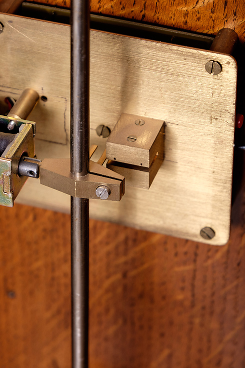
This version is a complete re-design as there were still too many variables at play in the older designs. The means of impulse to the pendulum is now by means of an air-cored coil beside the pendulum, acting on a horizontally mounted iron armature moving within the air core, and attached to the pendulum above the pendulum bob. Two IR opto beams are again used, one to generate seconds, and the other to detect arc. The electronics is reduced to a PIC microcontroller for all detection, logic and timing purposes. Using a microcontroller, the circuit is basically one chip, plus a Schmitt trigger chip to shape incoming puises.
The completed clock has been built into a dedicated case which originally housed a TMC 1-second pendulum master clock. The case and its accompanying pendulum were the only parts of the donor clock remaining when it was purchased.
The pilot dial in the case uses a Gents C400A silent seconds movement. The case, pendulum and pilot dial movement are the only parts that were commercially manufactured - all other parts have been made specifically for the clock.
As the flag that breaks the optical beams points rear-wards from the pendulum rod, a pendulum suspension had to be devised that did not allow the rod to rotate about its axis. A conventional spring suspension was not suitable, so the current implementation uses ball races. This has proved to work well. The clock now maintains a very stable rate. Detection of the falling arc (the Hipp toggle principle) is sufficiently accurate that impulse to the pendulum occurs every 6 or 8 seconds. I was concerned that, as the ball races are oscillating over a relatively small arc rather than continuousluy rotating, dirt would accumulate and affect the freedom of the suspension. If this proves to be the case, the pendulum suspension will have to be modified, probably to a knife-edge design.
|
|
|
|
|
|