In the circuit schematic below, dotted rectangles round groups of components denote a sub-assembly to the main board with numbers identifying connections.
Brief description of the circuit.
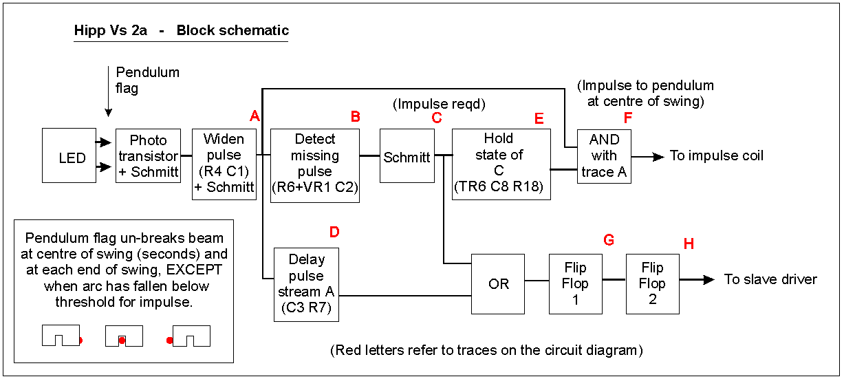
1). There is a single IR LED pair placed at pendulum dead centre at the bottom of the pendulum (1-second pendulum). The impulse coil is below the pendulum with an armature attached to the lower end of the pendulum. There is a flag which interrupts the IR beam mounted on the armature. The flag has a single cut out slot at dead centre - see the sketch, lower right of the graphic. The flag is wider on the right-hand side than the left and the impulse coils are offset to the right slightly to force impulse to occur in a left to right direction. The circuit looks for a missing pulse (Trace A) at the extreme left end of travel and then triggers impulse starting at the beginning of the next centre IR pulse and ending at the end of that centre IR pulse. The width of the central slot determines the start and duration of impulse. The slave dial is a Gents silent alternating polarity 1-second slave with a low impedance coil - approx 3 ohms.
2). The output of the IR receiver (TR1) is squared up by a Schmitt inverter (IC1, pins 1&2). This pulse can be very short as the pendulum approaches the Hipp trigger point, so the pulse is used to make TR2 short out C1. The time constant of C1,R4 widens the very short pulses. This is required later. The wider pulses are schmitt inverted again (IC1, pins 13&12).
3). TR3, R6, VR1, C2 is the network that detects the missing pulse. If the pulse is there, TR3 shorts out the rising charge in C2 before it reaches logic '1'. When the pulse is missing, C2 reaches logic '1'. (Trace B). This is Schmitt shaped (IC1 pins 5&6) and inverted (IC1 pins 9 & 8) to give a pulse (Trace C) that denotes 'impulse required'. TR6 then allows C8 to charge up rapidly to hold the pulse, and R18 allows it to discharge slowly so that the 'impulse required' logic 1 condition is held until the next centre IR pulse has been completed. This is then ANDed with the next centre IR pulse by IC4 to trigger impulse start and end to be the width of the centre pulse. The pulse on Trace C is also used to fill in the missing pulse in Trace A to keep the seconds ticking away. But because the start of the next centre pulse is coincident with the end of the Trace C pulse, a separate, slightly delayed, version of Trace A is derived by R7 & C3 (Trace D) which is ORed with Trace C into flip-flop 1 (1/2 IC3 - Trace G). The second flip-flop then evens out the seconds pulses to give a 2-second period (Trace H), which is an alternating Q output that changes every second. Just what the slave dial needs!
4). The slave driver allows C9 & C10 to charge up through the low impedance slave when the output of flip-flop 2 is high through TR8, and the Cs discharge through the slave and TR9 when the FF2 goes low.
5). Flip-flop G must be in the correct condition when the centre IR pulse occurs, otherwise the seconds pulses driving the slave are incorrect when impulse occurs. See the panel lower right of the graphic for the correct sequence.